Using the Volume Measurement Tool
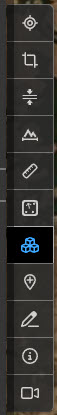
You can use the Volume Measurement tool to measure the volume and surface area of selected regions of a point cloud. The tool is primarily aimed at computing volumes and surface areas of 2.5D terrain regions - it will not necessarily be suitable for areas of a point cloud where there are points at multiple heights (e.g. trees with ground underneath), as the sampling of the points may result in spikes between the points at different elevations. To activate the tool, click the Volume Tool button from the tool palette as shown below.
Please note, the volume measurement tool is not available through guest sharelinks unless the guest has a Pointerra account.
Creating a new volume measurement
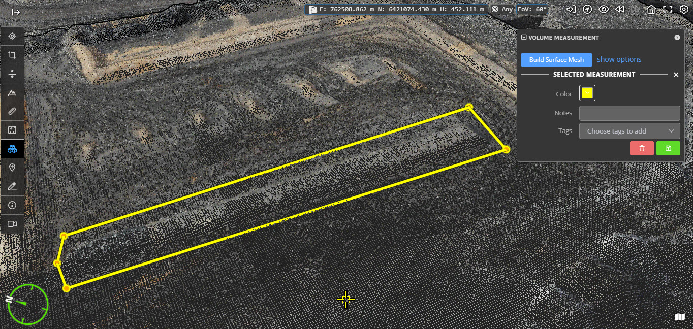
To begin, activate the tool and left click on the point cloud to begin drawing points that define a boundary around the region of interest. Press the escape key to cancel the current measurement or the enter key to confirm that the boundary is complete (you must select at least 3 points). The base surface for the volume calculation will be created from the points that you select. Depending on the desired base surface (see below), you should ensure that you select a suitable set of points for the external polygon.
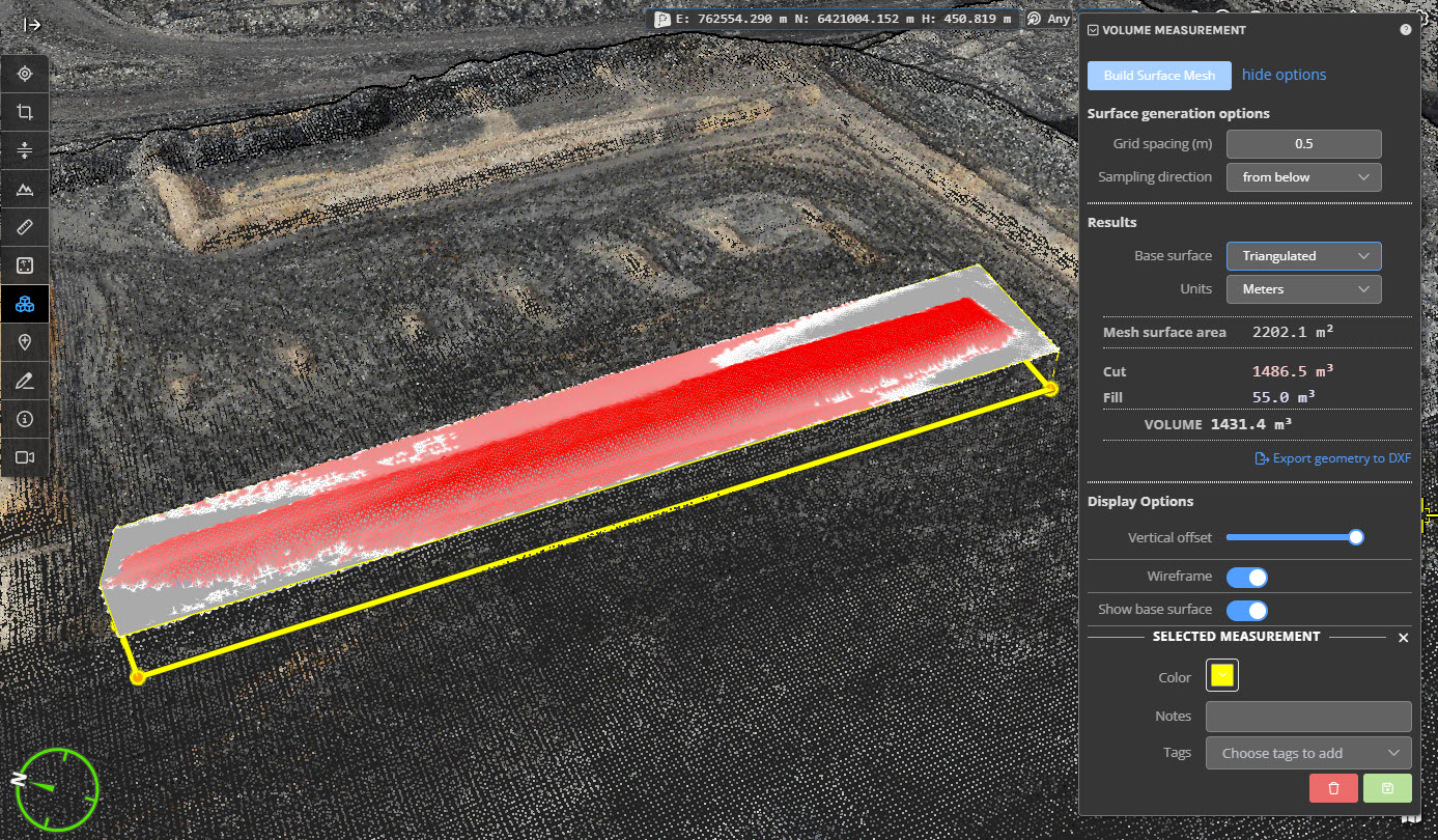
In the volume measurement panel (which will be located at the top right of the viewer), click the Build Surface Mesh button to create a 2.5D surface mesh by sampling the point cloud within the region that you defined. For classified point clouds, the mesh generation will take into account the classification visibility settings allowing you to exclude points based on their classification. The mesh generation process will use default options in this case, but you can customize some of the parameters if required - see mesh generation options for more details on advanced options.
From this mesh the volume and surface area will automatically be calculated between the generated mesh and the selected base surface.
Creating a boundary polygon from a CSV file
Instead of drawing a polygon, you can instead load a CSV or JSON file containing the set of coordinates to define the boundary polygon. Use the Load from FIle button to load the file.
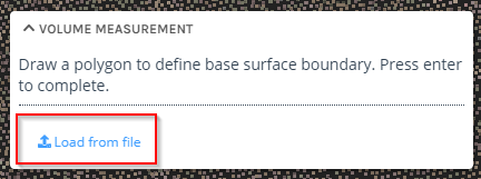
The CSV file should contain one 3D coordinate per line, with X, Y, and Z values comma separated on each line. There is no need to close the polygon by including the first vertex again.
Mesh generation options
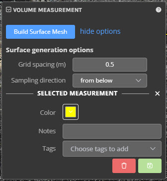
There are several options that allow you to fine tune the mesh generation. The mesh generating options can be found by clicking show options next to the Build Surface Mesh button. For most use cases, these settings will not need to be changed, but they can have a small impact on the calculated volume and generated mesh in certain circumstances.
Grid Spacing - the distance between sample points in the resulting mesh. A lower grid spacing creates a more detailed mesh and also takes longer to generate. There is an internal limit that is used to ensure that the sampling can complete in a reasonable amount of time, so for very large areas, the value that is actually used may end up being less than what you enter. Note: make sure you press enter, or click on the accept button to update the value after changing it.
Sampling Direction - whether to create the mesh by sampling the point cloud from above or from below. In most cases, sampling from below (taking the lowest points) will be the desired method. However, if there are noise points or other artifacts under the terrain, you may need to switch to sampling from above.
Note that changing these settings will mean you need to rebuild the surface mesh again - the other information in the panel will grey out/disable to indicate this.
Base surfaces
In order to calculate the volume of the region, you must specify a base surface that the mesh is compared to. After generating the surface mesh, you can freely switch between different base surfaces without having to regenerate the mesh, the new volume will automatically be calculated. There are several base surfaces to choose from, each of them are useful in specific situations. By default a triangulated base surface is used.
Min height - Use a horizontal plane at the minimum height of the points you selected
Max height - Use a horizontal plane at the maximum height of the points you selected
Average height - Use a horizontal plane at the average height of all the points you selected
Custom height - Use a horizontal plane at a height that you specify
Best fit plane - Create a plane that fits through all the points that you selected
Triangulated - Create a triangulated surface mesh with vertices at the points that you selected (this is the default base surface)
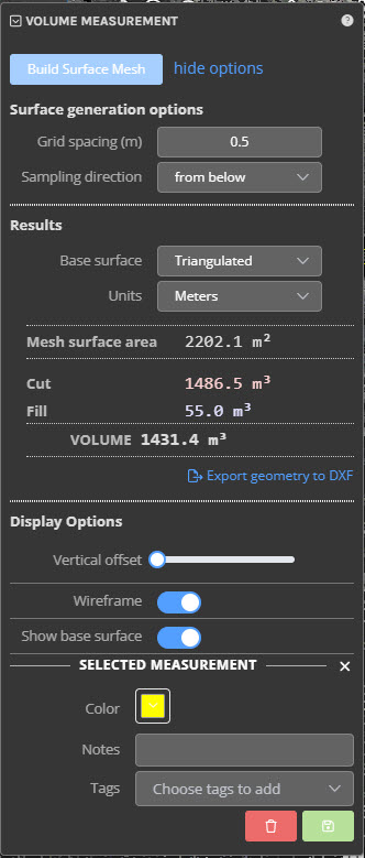
Results
The calculated volume and surface area values are shown in the results section. The total volume is split into two components - Cut and Fill. Cut represents the volume that was above the base surface while fill represents the volume below the base surface. Total volume is reported as the difference between the cut and fill volumes.
The generated mesh is coloured to reflect the calculated cut and fill volumes. Red vertices are those which are above the base surface and contributed to the cut volume, blue vertices are those that are below the base surface and contributed to the fill volume. White vertices are those which are within 10cm of the base surface (note that they still count towards the cut and fill volumes).
Display options
Below the results are display options for viewing the base surface and the generated mesh.
Vertical Offset - Move the mesh and base surface up so that you can view the point cloud without the mesh obstructing your view
Wireframe - Render the generated mesh as triangle outlines (wireframe) or as a solid surface
Show base surface - hide or show the base surface
Editing a volume measurement
You can select an existing volume measurement by either clicking on the measurement's mesh in the 3D view or clicking on it in the measurements section of the left panel. To edit the measurement, you must have the volume measure tool activated. You can move any of the points that define the boundary by left clicking and dragging the point to define a new boundary. Moving the boundary points will invalidate the mesh and volume calculations and this is indicated by hiding the mesh and greying out the results. When you have made all the changes that you want, click Build Surface Mesh to regenerate and recalculate the volume and mesh.
You can also edit the Mesh generation options for an existing measurement. Doing so will also invalidate the mesh and calculated volume.
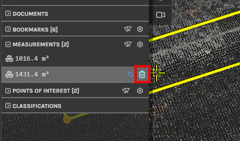
Deleting a measurement
To delete a volume measurement you can either find it in the measurements group in the left panel and click the small "x" that appears when hovering over it or right click on the 3D representation (the generated mesh or the boundary outline) and select delete from the context menu that appears.
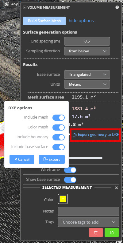
Exporting results to DXF
You can export the created geometry data, including: mesh, colour mesh, boundary and base surface to a DXF file. Each of these objects will be placed into a separate layer in the exported DXF file.
Once you have generated a mesh, click on the Export geometry to DXF button to initiate the DXF generation.
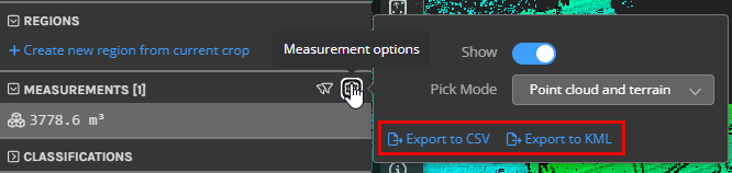
Exporting results to CSV/KML
You can export the created measurement results to a CSV/KML file but navigating to the Measurements tab, click to the measurements options and select either Export to CSV or Export to KML.