Using the Plan Section Tool
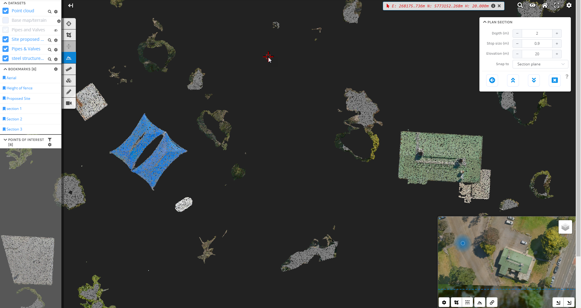
Plan sections are similar to the cross sections, but they allow you to view a horizontal slice through the point cloud, with a defined width and orientation. When in plan section viewing mode, the viewer changes to an orthographic camera (rather than the normal perspective camera used in the 3D view) to allow easy measurement and visualization of features. The mouse controls will also change to only permit panning, rotating and zooming. You cannot leave the plan section view into the free camera mode, like you can in the cross section tool.
Creating a Plan Section
You can create, view and export plan sections in the 3D viewer by activating the Section Tool from the tool palette (1) and ensuring that the section type is set to Plan Section (2).

Once the tool is active, start by selecting a point by left clicking on a point in the 3D viewer. This will define the elevation of the plan section. A plan section will be generated and the 3D view will switch into plan section viewing mode.

Navigating a Plan Section
Once in the plan section view mode, your navigation is limited to panning, rotating and zooming in a top-down view.
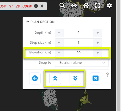
The arrow buttons move the elevation of the plan section up and down. You can also specify the elevation with a manual input:
All of the navigation buttons can be done using the keyboard shortcuts listed below:
| Key Shortcut | Effect |
|---|---|
| Up Arrow | Increase plan elevation |
| Down Arrow | Decrease plan elevation |
| Middle Mouse Button | Rotate plan section in mouse direction (left or right) |
Editing a Plan Section
You can use the right-click context menu to access a number of shortcut actions that are specific to the plan section mode.
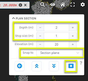
The depth of the plan section (how many meters orthogonal to the plan section will be included) can be controlled using the Plan Section tool panel that will be displayed in the upper right of the viewer window when plan section mode is active. When moving the elevation, the amount by which you increase or decrease by (step) can be adjusted with the step size input.
The Snap to option influences the way the mouse picker determines the coordinate from the mouse position. In 3D points mode the coordinate is determined from the closest point (yellow crosshair) or 3D model (green crosshair). In Section plane mode the coordinate is determined by projecting the mouse position onto the section plane (red crosshair), this mode is especially useful for measuring and annotating where there are no points.
You can exit the tool by pressing Exit cross section from the Cross section tool panel or by pressing the ESCAPE key when drawing a cross section.

