Using the Cross Section Tool
Cross sections allow you to view a vertical slice through the point cloud, with a defined width and orientation. When in cross section viewing mode, the viewer changes to an orthographic camera (rather than the normal perspective camera used in the 3D view) to allow easy measurement and visualisation of features. The mouse controls will also change to only permit panning and zooming. You will not be able to rotate the view, as the camera is constrained to always look orthogonal to the direction of the section.
Creating a Cross section
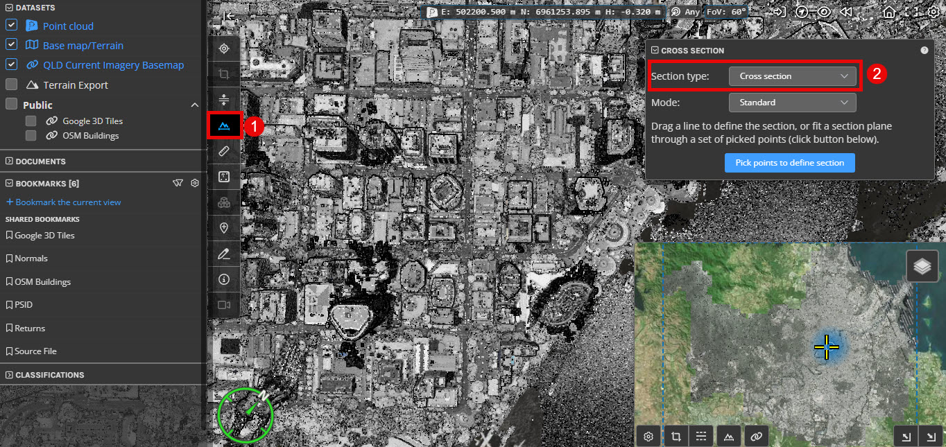
You can create, view and export cross sections in the 3D viewer by activating the Section Tool from the tool palette, or from the overview map (1) and ensuring that the section type is set to Cross Section (2).
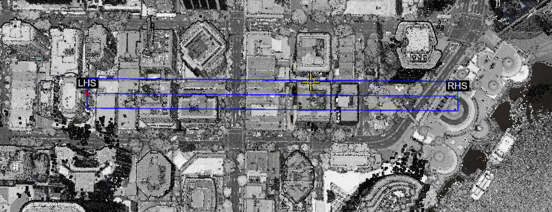
Once the tool is active, start by selecting a starting point by left clicking on a point in the 3D viewer and either select a second point or hold and drag to create a line. A cross section will be generated and the 3D view will switch into cross section viewing mode. Note that the first selected point will be the left hand side of the cross section (indicated by a red point on the 2D map view) and the second selected point will be the right hand side (indicated by a green point on the 2D map view).
Alternatively, you can define a cross section from the 2D map view. Activate the cross section tool in the map tools palette and draw your desired section line on the 2D map view.
Navigating a Cross section
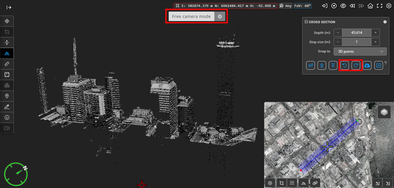
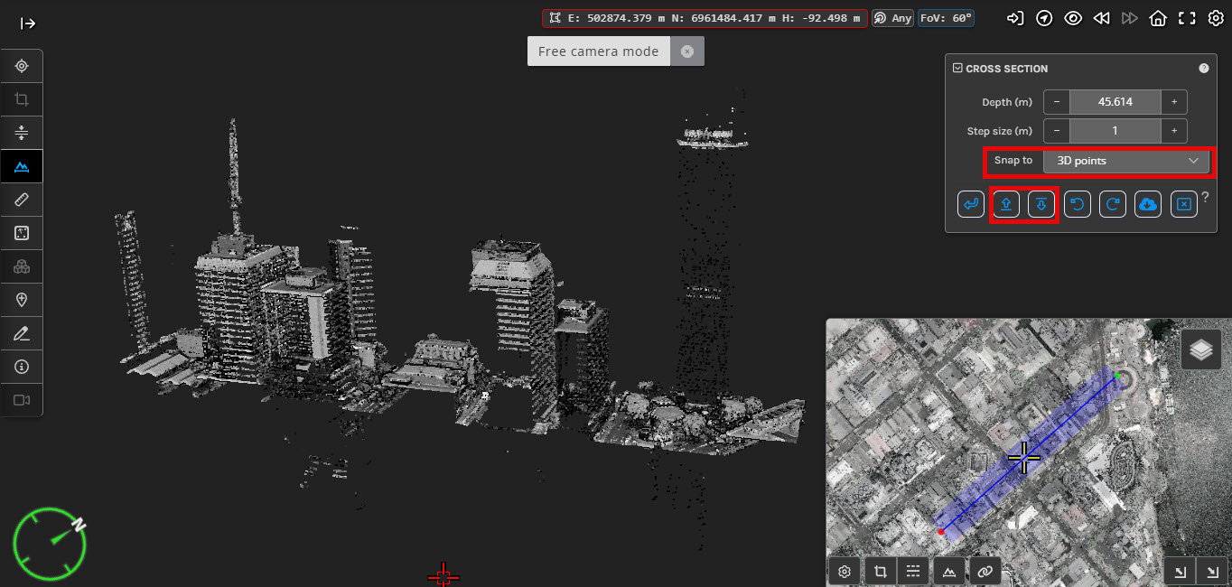
Once in the cross section view, you can enter free camera mode using middle mouse button, by which you can view and interact with the cropped section from any desired angle/view. There are also rotate left/right buttons (highlighted below) that can allow you to incrementally rotate around the cross section.
Editing a Cross section
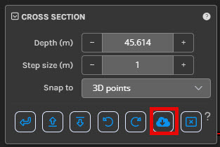
The depth of the cross section (how many metres orthogonal to the cross section will be included) can be controlled using the Cross Section tool panel that will be displayed in the upper right of the viewer window when cross section mode is active. The arrow buttons move the cross section region, and the size of these adjustments can be changed using the Step Size parameter in the Cross Section tool panel. Each of these arrows have keyboard shortcuts listed below.
Key Shortcut |
Effect |
Up Arrow |
Step cross section forward |
Down Arrow |
Step cross section backward |
Left Arrow |
Step cross section left |
Right Arrow |
Step cross section right |
< |
Rotate cross section towards the left |
> |
Rotate cross section towards the right |
Shift + Middle Mouse Button |
Rotate cross section in mouse direction (left or right) |
You can also use the right-click context menu to access a number of shortcut actions that are specific to the cross section mode.
The Snap to option influences the way the mouse picker determines the coordinate from the mouse position. In 3D points mode the coordinate is determined from the closest point (yellow crosshair) or 3D model (green crosshair). In Section plane mode the coordinate is determined by projecting the mouse position onto the section plane (red crosshair), this mode is especially useful for measuring and annotating where there are no points.
Use the back arrow button in the Cross section tool panel to return to the 3D view where you can modify the cross section by dragging the end points (white points that turn green when hovered over) or redraw the section using the Redraw section button in the Cross section tool panel.
You can exit the tool by pressing Exit cross section from the Cross section tool panel or by pressing the ESCAPE key when drawing a cross section.
Exporting a Cross section
Once you have created a cross section you will have the option to export the points within the section. You can export the points by pressing the Export section points button in the Cross section tool panel and following the instructions (seeing Exporting Points for more details on exporting data).